DS1104 R&D Controller Kit
Cost-effective single-board system for controller development
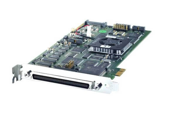
The DS1104 R&D Controller Board upgrades a PC to a development system for rapid control prototyping. The board can be installed in virtually any PC with a free PCI or PCIe slot.

At A Glance
Application Areas
The real-time hardware based on PowerPC technology and its set of I/O interfaces make the controller board an ideal solution for developing controllers in various fields, such as drives, robotics, and aerospace. The board is used in many university laboratories.
Key Benefits
The DS1104 R&D Controller Board is a cost-effective entry-level system with I/O interfaces and a real-time processor on a single board that can be plugged directly into a PC. It upgrades your PC to a development tool for rapid control prototyping and is ideal for developing smaller control applications or for education purposes. Real-Time Interface (RTI) provides Simulink® blocks for graphical I/O configuration. The board can be installed in virtually any PC with a free PCI or PCIe slot.
Using Real-Time Interface
With Real-Time Interface (RTI), you can easily run your function models on the DS1104 R&D Controller Board. You can configure all I/O graphically, insert the blocks into a Simulink block diagram, and generate the model code via Simulink® Coder™. The real-time model is compiled, downloaded, and started automatically. This reduces the implementation time to a minimum.
Technical Details
| Parameter | Specification | |
| Processor | MPC8240 processor with PPC 603e core and on-chip peripherals | |
| 64-bit floating-point processor | ||
| CPU clock: 250 MHz | ||
| 2 x 16KB cache, on-chip | ||
| Memory | Global Memory | 32 MB SDRAM |
| Flash memory | 8MB | |
| Timer | 4 general-purpose timers | 32-bit down counter |
| Reload by hardware | ||
| 80-ns resolution | ||
| 1 sampling rate dimer (decrementer) | 32-bit down counter | |
| Reload by hardware | ||
| 40-ns resolution | ||
| 1 time base counter | 64-bit up counter | |
| 40-ns resolution | ||
| Interrupt controller | 5 timer interrrupts | |
| 2 incremental encoder index line interrupts | ||
| 1 UART interrupt | ||
| 1 slave DSP interrupt | ||
| 1 slave DSP PWM interrupt | ||
| 5 A/D converter (end of conversion) interrupts | ||
| 1 host interrupt | ||
| 4 external interrupts (user interrupts) | ||
| A/D converter | Channels | 4 multiplexed channels equipped with one sample & hold A/D converter (1×16-bit) |
| 4 parallel channels, each equipped with one sample & hold A/D converter (4×12-bit) | ||
| Note: 5 A/D converter channels (1×16-bit and 4×12-bit) can be sampled simultaneously | ||
| Resolution | Multiplexed channels: 16 bit | |
| Parallel channels: 12 bit | ||
| Input voltage range | ±10 V | |
| Conversion time | Multiplexed channels: 2 µs1) | |
| Parallel channels: 800 ns1) | ||
| Offset error | ±5 mV | |
| Gain error | Multiplexed channels: ±0.25% | |
| Parallel channels: ±0.5% | ||
| Offset drift | 40 µV/K | |
| Gain drift | 25 ppm/K | |
| Signal-to-noise ratio | Multiplexed channels: >80 dB | |
| Parallel channels >65dB | ||
| D/A converter | Channels | 8 channels |
| Resolution | 16-bit | |
| Output range | ±10 V | |
| Settling time | Max. 10 µs (full-scale, accuracy ½ LSB) | |
| Offset error | ±1 mV | |
| Gain error | ±0.1% | |
| Offset drift | 130 µV/K | |
| Gain drift | 25 ppm/K | |
| Signal-to-noise ratio | >80 dB | |
| Imax | ±5 mA | |
| Digital I/O | Channels | 20-bit parallel I/O |
| Single bit selectable for input or output | ||
| Voltage range | TTL input/output levels | |
| Iout, max | ±5 mA | |
| Parameter | Specification | ||
| Digital incremental encoder interface | Channels | 2 independent channels | |
| Selectable single-ended (TTL) or differential (RS422) input (software-programmable for each channel) | |||
| Position Counters | 24-bit resolution | ||
| Max. 1.65 MHz input frequency, i.e., fourfold pulse count up to 6.6 MHz | |||
| Counter reset or reload via software | |||
| sensor supply voltage | 5 V/0.5 A | ||
| Serial interface | Configuration | Single UART (universal asynchronous receiver and transmitter) with FIFO | |
| PLL-driven UART for accurate baud rate selection | |||
| RS232/RS422/RS485 compatibility | |||
| Baud rate | Up to 115.2 kBd (RS232) | ||
| Up to 1 MBd (RS422/RS485) | |||
| Slave DSP | Type | Texas Instruments TMS320F240 DSP | |
| 16-bit fixed-point processor | |||
| Clock rate | 20 MHZ | ||
| Memory | 64Kx16 external code memory | ||
| 28Kx16 external data memory | |||
| 4Kx16 dual-port memory for communication | |||
| 32KB flash memory | |||
| I/O channels 1) | 10 PWM outputs | ||
| 4 capture inputs | |||
| 1 serial peripheral interface | |||
| Input voltage range | TTL input/output level | ||
| A/D converter inputs: 0 … 5 V | |||
| Output current | Max. ±13 mA | ||
| Host interface (requires one PCI or one PCIe x 1 slot) | PCI | PCIe | |
| Physical characteristics | Physical size | 185 x 107 mm (7.28 x 4.2 in) | 220 x 111 mm (8.66 x 4.3 in) |
| Ambient temperature | 0 … 55 ºC (32 … 131 ºF) | 0 … 55 ºC (32 … 131 ºF) | |
| Cooling | Active cooling by fan | Active cooling by fan | |
| Power consumption | 18.5 W | Please inquire | |
| Power supply | +5 V ±5%, 2.5 A | Please inquire | |
| +12 V ±5%, 0.3 A | |||
| 12 V ±5%, 0.2 A | |||


